Etched Implants: A Comparative Surface Analysis of Four Implant Systems
Etched Implants: A Comparative Surface Analysis of Four Implant Systems
Acid etching: Comparison between surface parameters and roughness of four different etching method
It has been shown previously that the surface roughness of dental implants affects the osseointegration, ossification, and anchorage of the implant to the bone [1-8]; therefore, many manufacturers apply special treatments designed to increase the roughness of the implant surface. One of the most common roughening methods is an acid etching, and implants treated with this method have been shown to improve the results in various loading tests [1,3,5-10] and reduce healing time [11-14]. Acid etching uses acids to create pits in the surface of the titanium implant and can be combined with other methods such as sandblasting.
The research presented here [15] compares four implants, all acid-etched but using different systems and protocols, to examine the difference between the systems and the replications of the industrial manufacturing process. In order to ensure that the implants were manufactured from three different batches, three different implants with different lengths and sterilization dates were chosen for each system.
The four systems examined:
DPS-Frialit II: Manufactured by Friatech AG (Mannheim, D). Implants are processed using sand-blasting and acid-etching, though details regarding the etching protocol could not be found.
Osseotite: Manufactured by 3i (Palm Beach Gardens, FL). Implants are processed using dual thermo-etching, which includes etching in a mixture of acids and heating to create surface roughness.
SLA-ITI: Manufactured by Straumann AG (Waldenburg, CH). Implants are sand-blasted with large grit alumina and etched in a heated mixture of acids.
HaTi: Manufactured by HaTi Dental AG (Bettlach, CH). Implants are sand-blasted and -etched, though no information regarding the etching process was found.
The four systems examined:
Roughness measurement:
Roughness was measured using a Hommel T8000 profilometer
(Hommel AG, Hamburg, D).
The parameters inspected were: Ra – average of absolute deviation from
the mean line; Rq – root means square value of the profile departure.
More sensitive than Ra;
Rsk – skewness, the symmetry of the deviation from a mean plane
(negative – more valleys, positive – more peaks);
RzISO – an average of the five highest peaks and five lowest valleys over
the entire measurement trace.
Rt – maximal peak to valley value of the entire measurement trace.
Indicates poor processing or scratches;
Sm – average spacing between the falling flanks of peaks on the mean line.
RΔq – root means the square slope of the profile over the measured length.
All values are indicated in Table 1.
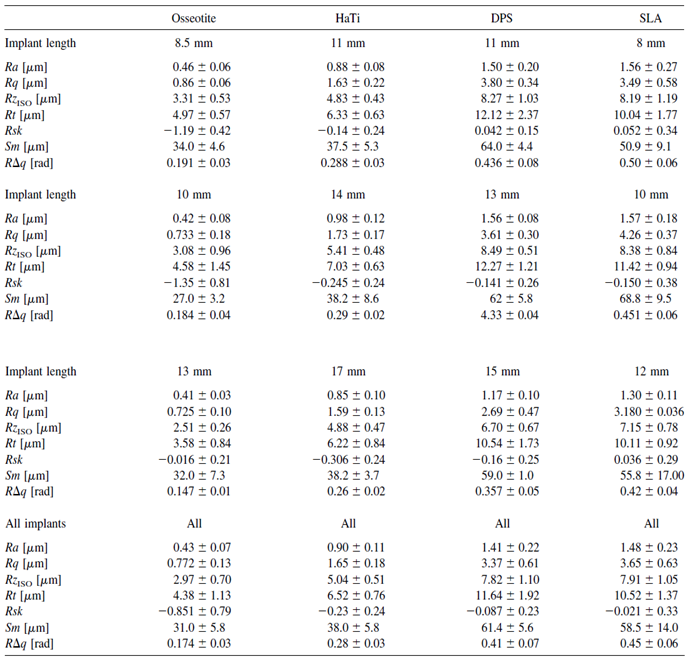
Table 1: Various parameters regarding the surface values of the four implants.
In order to check the differences in the seven roughness parameters
shown in Table 1 for each of the etching methods, the p-value was
calculated for all three implants from each method.
The results are shown in Table 2.
Only the HaTi implants presented the same values for each of the
roughness parameters, while the implants from the other three –
Oseeotite, SLA, and DPS – showed significant differences between
the implants in two to four parameters.
Significant differences between the three implants, which supposedly
present the same characteristics, imply possible problems or defects
in the manufacturing process.
In order to check the differences in the seven roughness parameters shown in Table 1 for each of the etching methods, the p-value was calculated for all three implants from each method.
The results are shown in Table 2.
Only the HaTi implants presented the same values for each of the roughness parameters, while the implants from the other three – Oseeotite, SLA, and DPS – showed significant differences between the implants in two to four parameters.
Significant differences between the three implants, which supposedly present the same characteristics, imply possible problems or defects in the manufacturing process.
Table 2: Statistical analysis of the various surface roughness parameters. P-value was calculated for the values of the three different implants of each etching system. S = statistically significant difference between the three implants. NS = No statistically significant difference between the three implants.
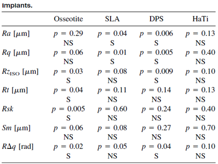
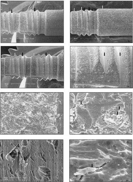
The next stage was imaging the surfaces of the implants using scanning electron microscopy (SEM). The results were as follows:
DPS-Frialit II: All three implants showed the same surface characteristics [Figure 1. a-c], but surprisingly there were two different surface patterns that developed [Figure 1.d]. Some areas, such as the flat cervical and epical areas and the tips of the threads, were sand-blasted [Figures 1.e,f], while others, such as the core of the thread, were not sand-blasted, and therefore were not roughened. Alumina particles can be seen (white spots), sometimes weakly attached to the surface of the implant [Figure 1.f]. The etching appears to be rather weak, the micro-roughness is limited, and the pits are too shallow to allow bone ingrowth [Figure 1.f,g,h]; however, the surface seems replicable.
Osseotite: Two areas – machined and etched – can be seen. In all three implants, the cervical threads remained machined, while the apical areas were etched [Figure 2.a-d]. The etching was moderate and created pits in the surface. No contamination was found, and the surface presented micro-scale roughness and deep pits. The surface seems replicable.
SLA-ITI: A large amount of alumina particles remained from the roughening process, indicated as white spots [Figure 3.a-c]. Two different patterns were observed, since some areas were not sand-blasted (Figure 3.d), but rather machined and etched. The 10-mm-long implant seems smoother than the 8-mm-long implant, and the 12-mm-long implant seems to be the smoothest of all three (Figure 3.e-g). The rougher the surface was, the more contamination by alumina particles was observed. Deep pits, created by the etching process, which encourage bone growth, are visible (Figure 3.i-j). The surface displayed micro-and-macro roughness; however, it was not replicable.
HaTi: A significant amount of particles remained from the blasting process [Figure 4.a—c]. The etching pattern was similar in all areas of the implant, and the etching process produced round and wide pits [Figure 4.d-f). The roughness appeared on the macro-and-micro scale, and the surface seems replicable.
Figure 1. SEM micrographs of the surface of the DPS-Frialit II implants:
11-mm-long (a),
13-mm-long (b),
and 15-mm-long (c).
White spots indicate alumina particles, white arrows point to the blasted area and black arrows point to non-blasted areas.
Area (d) presents blasted and non-blasted areas, the non-blasted surface matching the interthread area.
Area (e) presents the sand-blasted area of the surface.
Area (f) shows a high magnification of sand-blasted and acid-etched areas.
Area (g) is a high-magnification view of the non-sand-blasted area.
Area (h) is the surface of the implant at high magnification.
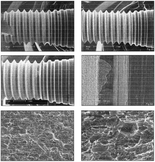
Figure 2:
SEM micrograph of the implant surface of the
Osseotite 8.5-mm-long (a),
10-mm-long (b)
and 13-mm-long (c) implants.
Area (d) shows the transitional area between the machined and etched zones.
Area (e) is a high-magnification view of the moderate etching and consistent pits.
Area (f) is a high-magnification view of the pits created by the dual-thermal etching manufacturing process.
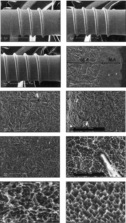
Figure 3:
SEM micrographs of the surface of the SLA-ITI 8-mm-long (a),
10-mm-long (b) and
12-mm-long (c) implants.
White spots indicate alumina particles.
Area (d) is the transitional area between the neck and SLA surface of the implant.
White arrows point to where the grain boundaries of the metal were exposed.
Macroroughness of the 8-mm-long (e),
10-mm-long (f) and
12-mm-long (g) implants.
Area (h) is a high-magnification view of the macro-and-microroughness.
Microroughness of the SLA
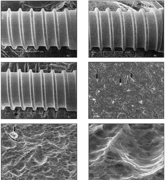
Figure 4: SEM micrographs of the surfaces of the HaTi 11-mm-long (a), 14-mm-long (b), and 17-mm-long (c) implants. White spots indicate alumina particles. Black arrows mark alumina particles (d). Area (e) is a higher magnification of the sand-blasted and etched surface. Area (f) is a picture of the pits of the surface, which are rounded, and wide without undercuts.
The efficiency of the etching process used to create the pits and roughen the surface, also varied between methods, although this is unclear if, and what, the effect it has on the efficiency of the implant in terms of bone formation.
The method used for the DPS-Frialit II created pits that were too small to enable bone growth, and the sand-blasting was inconsistent, with some areas remaining un-blasted. This aspect of the implants was not mentioned in literature or advertising materials. Numerous small particles remained weakly attached to the surface.
The SLA implants also featured a transitional zone between the SLA and machined surface, which was not mentioned in the literature or advertising materials. This can be due to changes in the manufacturing process during the blasting step. The roughness and amount of particles varied between the implants indicating that the manufacturing process can be improved.
The HaTi surface displayed rounded and wide pits rather than deeper, sharper ones. This shape is usually created by pickling rather than etching [5] a process that might result in low torque values. Further experiments should be performed to determine if this surface has similar bone interlocking abilities to other surfaces [6,8].
The final conclusion by the author refers to two aspects of the implants: manufacturing and publications. The study revealed that the manufacturing process is not fully replicable and that the information provided by implant companies is not accurate enough and does not provide the full picture regarding the characteristics of the implants. This applies, for example, to the roughness of the implants mentioned by the manufacturers, as the values provided by them, such as in the case of the SLA implant, did not match the values measured in this survey.
Bibliography:
1. Buser D, Schenk RK, Steinemann SG, Fiorellini JP, Fox CH, Stich H. Influence of surface characteristics on bone integration of titanium implants: A histomorphometric study in miniature pigs. J Biomed Mater Res 1991;25:889 –902.
2. Szmukler-Moncler S, Reingewirtz Y, Weber HP. Bone response to early loading: The effect of surface state. In: Davidovitch Z, Norton LA, editors. Biological mechanisms of tooth movement & craniofacial adaptation. Boston: Harvard Society for the Advancement of Orthodontics; 1996. p 611–616.
3. Cochran DL, Schenk RK, Lussi A, Higginbottom FL, Buser D. Bone response to unloaded and loaded titanium implants with a sandblasted and acid-etched surface: A histometric study in the canine mandible. J Biomed Mater Res 1998;40:1–11.
4. Szmukler-Moncler S, Perrin D, Ahossi V, Pointaire P. Evaluation of BONIT, a fully resorbable calcium phosphate (CaP) coating obtained by electrochemical deposition, after 6 weeks of healing: A pilot study in the pig maxilla. Key Eng Mater 2001;192–195:395–398.
5. Wilke HJ, Claes L, Steinemann S. The influence of various titanium surfaces on the interface shear strength between implants and bone. In: Heimke G, Solte´sz U, Lee AJC, editors. Clinical materials. Amsterdam: Elsevier; 1990. p 309–314.
6. Wong M, Eulenberger J, Schenk R, Hunziker E. Effect of surface topology on the osseointegration of implant materials in trabecular bone. J Biomed Mater Res 1995;29:1567–1575.
7. Klokkevold PR, Johnson P, Dadgostari S, Caputo A, Davies JE, Nishimura RD. Early endosseous integration enhanced by dual acid etching of titanium: A removal torque study in the rabbit. Clin Oral Implant Res 2001;12:350 –357.
8. Szmukler-Moncler, S, Perrin D, Bernard JP, Pointaire P. Biological properties of acid etched titanium surfaces: Effect of sandblasting on bone anchorage. J Biomed Mater Res Appl Biomater (in press).
9. Lazzara RJ, Testori T, Trisi P, Porter SS, Weinstein RL. A human histologic analysis of Osseotite and machined surfaces using implants with 2 opposing surfaces. Int J Periodont Rest Dent 1999;19:3–16.
10. Baker DA, London RM, O’Neil RB. Rate of pull-out strength gain of dual-etched titanium implants: A comparative study in rabbits. Int J Oral Maxillofac Implants 1998:14:722–728.
11. Lazzara RJ, Porter SS, Testori T, Galante J, Zetterquist LA. A prospective multicenter study evaluating loading of Osseotite implants two months after placement. J Esthet Dent 1998;10: 280–289.
12. Roccuzzo M, Bunino M, Prioglio F, Bianchi SD. Early loading of sandblasted and acid etched (SLA) implants: A prospective split-mouth comparative study. Clin Oral Implant Res 2001;12: 572–578.
13. Cochran DL, Buser D, ten Bruggenkate C, Weingart D, Taylor TM, Bernard JP, Simpson JP, Peters F. The use of reduced healing times on ITI implants with a sandblasted and acid-etched (SLA) surface. Early results from clinical trials on SLA implants. Clin Oral Implant Res 2002;13:144 –153.
14. Testori T, Del Fabbro, M, Feldman S, Vincenzi G, Sullivan G, Rossi R Jr, Anitua E, Bianchi F, Francetti L, Weinstein RL. A multi-center prospective evaluation of 2-months loaded Osseotite implants in the posterior jaws: 3-year follow-up results. Clin Oral Implant Res 2002;13:154 –161.
15. Szmukler-Moncler S, Testori T, Bernard JP. Etched implants: comparative surface analysis of four implant systems. J Biomed Mater Res B Appl Biomater. 2004 5;69:46-57.
The combination of innovative surface technology with 344% stronger bone reduces marginal bone loss and provides for a higher BIC%, decreasing
the risk of peri-implant disease. The enhanced deep thread
simplifies the insertion and allows for high primary stability.
A wide variety of implant systems are offered in order to
suit the widest range of bone densities. Our technologies
are constantly being updated to offer a range of parts that
allow the flexibility that is vital to achieving the most
aesthetically pleasing results.
The combination of innovative surface technology with 344% stronger bone reduces marginal bone loss and provides for a higher BIC%, decreasing the risk of peri-implant disease. The enhanced deep thread simplifies the insertion and allows for high primary stability.
A wide variety of implant systems are offered in order to suit the widest range of bone densities. Our technologies are constantly being updated to offer a range of parts that allow the flexibility that is vital to achieving the most aesthetically pleasing results.


Stay Safe. Wear a Mask!
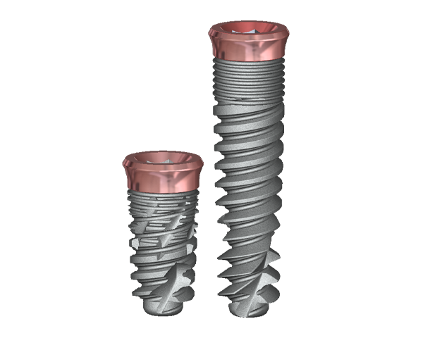
The pink tissue versatile implant neck combines superior gingival aesthetics and high primary stability, improved placement, and temporization,
which is particularly beneficial in
aesthetically demanding cases.
The pink tissue versatile implant neck combines superior gingival aesthetics and high primary
stability, improved placement, and
temporization, which is particularly
beneficial in aesthetically demanding
cases.
The pink tissue versatile implant neck combines superior gingival aesthetics and high primary stability, improved placement, and temporization, which is particularly beneficial in aesthetically demanding cases.